Create a Raycast Function
Tutorial Overview:
- Set up a level to use PhysX raycasting.
- Create a reusable function to Raycast to the mouse cursor.
- Create a Script Canvas graph using the Raycast function.
- Filter the raycasts based on PhysX Collision Groups.
Raycast to Cursor Function
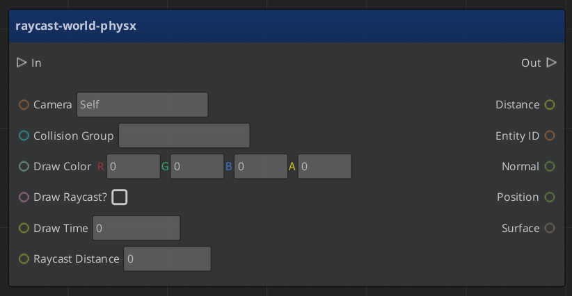
When the following function is used, if the mouse cursor is pointing to an entity in the level, the Entity ID, Distance from the camera, world-space Position as well as the Normal vector and Surface Crc32 at that position are returned.
If the mouse cursor is not pointed to a valid entity, if the entity is too far away, or the Collision Group does not match, the function does not trigger its output.
The Camera entity must be set to the active camera at the time of raycasting. Raycast Distance will limit how far entities can be from the camera's location to be considered valid targets of the raycast. PhysX Collision Groups are configured in the editor menu under Tools > PhysX Configuration. If the PhysX Configuration has not been altered, Collision Group set to the string 'Default' will allow the raycast function to hit all entities in the level. If the PhysX Terrain component has been added in Tools > Level Inspector, the terrain is also a valid target for the raycast.
If Draw Raycast? is set to True, the raycast will be drawn on-screen in the Draw Color for the Draw Time in seconds.
Note: The function's In and Out nodes are placed on the graph from the Script Canvas toolbar at the top of the graph.
The Function Node

Graph Variables
| Variable Name | Variable Type | Default Value | Scope |
|---|---|---|---|
| Camera | Entity ID | In | |
| Collision Group | String | Default | In |
| Draw Color | Color | 255,0,0,255 | In |
| Draw Raycast? | Boolean | True | In |
| Draw Time | Number | 1 | In |
| Raycast Distance | Number | 5000 | In |
| Camera World Location | Vector3 | Local | |
| Cursor Flip Y Axis | Vector2 | Local | |
| Cursor Position | Vector2 | Local | |
| Object Hit? | Boolean | Local | |
| Ray | Vector3 | Local | |
| Screen Height | Number | Local | |
| Distance | Number | Out | |
| Entity ID | Entity ID | Out | |
| Normal | Vector3 | Out | |
| Position | Vector3 | Out | |
| Surface | CRC | Out |
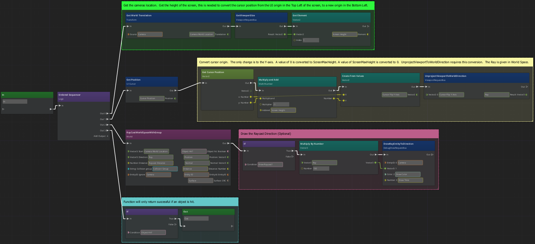
Graph of Function

How it Works
The graph uses the Ordered Sequencer from the Logic category to divide the function into four steps Out 0 - Out 3. Out 0 gets the world translation of the Camera entity and also gets the screen's height in pixels, this is needed for the next step.
In Out 1 we use the Get Position and UnprojectViewportToWorldDIrection nodes. While both nodes use a 2-dimensional coordinate system measured in pixels, the systems are not centered at the same origin. This step converts the cursor's coordinates. UnprojectViewportToWorldDIrection returns the ray (normalized) that will be used for the raycast.
In Out 2 the raycast is performed using the values that were supplied as inputs. If the Draw Raycast? input was set to True the rest of Out 2 is executed.
Finally, Out 3 checks if a valid entity was hit during the raycast. If the check succeeds, then the function is allowed to return the output values.